MHV Feedthroughs Cabling Instructions & Specifications
Features
- Feature grounded or floating shields
- Designed and rated for use in high and ultrahigh vacuum applications
- Suitable for cryogenic temperatures
- Single-ended assemblies come with one air-side cable connector, but without vacuum-side connectors. Options include power push-on contacts and vacuum cable assemblies
- Double-Ended assemblies come with air side only
Specifications Table
| Conductor Material | Stainless Steel |
| Insulator Material | Alumina |
| Cable | RG-59U |
| Connection | Bayonet |
| Temperature Range (for metal seals) | Weld adapter, CF: -200°C to +450°C |
| Temperature Range (for elastomer seals) | KF, O-Ring, NPT: To +150°C |
| Temperature Max. Ramp Rate | 25°C/Minute |
| Temperature Range (cable connectors) | -65°C to +165°C |
| Max. Voltage (for floating shields) | Shield-Ground: 2,500V DC Shield-Pin: 5,000V DC |
| Max. Voltage (for grounded shields) | 500V DC |
| Max. Current | 3A |
NOTE: Do not crossmate MHV feedthroughs with BNC feedthroughs. MHV feedthroughs are rated at higher voltages.
MHV Feedthroughs Cabling Instructions
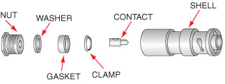
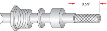
1) Place nut, washer, and gasket over cable jacket. V-groove should face toward cable end. Cut and strip cable jacket to 0.59" as shown.
2) Comb out braid and taper toward conductor center.
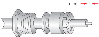
3) Slide clamp over braid, placing small end toward cable end. Push clamp against cable jacket; fold braid wires back over clamp and trim flush at large end of clamp. Trim dielectric to 0.13", being very careful not to nick conductor in the process. Wet conductor with a non-acid core 60–40 tin–lead solder.
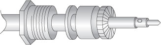
4) Slide contact pin onto conductor and solder in place using 60–40 tin–lead solder. Remove excess solder. Do not overheat cable dielectric because it may swell and prevent insertion of cable into the shell.
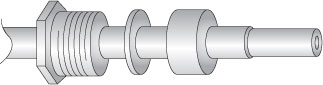
5) Slide cable assembly into shell as far as it will go. Then slide nut into shell. Hold cable and shell securely while tightening screw with wrench.