 |
The B-Factory project is more formally known as PEP-II. This is an upgrade to PEP-I, the original Positron Electron Polycolider built at the Stanford Linear Accelerator Complex (SLAC) in the seventies. The B-Factory utilizes two particle accelerator rings which are positioned one on top of the other in a roughly hexagonal tunnel. So basically, how does the B-Factory Work? For more detailed information about the B-Factory project, see their home page at http://www.slac.stanford.edu/accel/pepii/home.html.
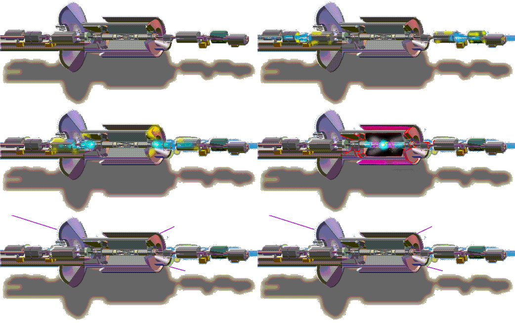
Animated GIF By Robin Lafever
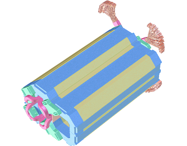
This is a preliminary SolidDesigner 3D model of the B-Factory Q2 magnet. This is a conventional magnet in which the core is made of steel and the coils use water cooled copper conductors. The coils are potted in epoxy (the pink structures) and held in place with non-magnetic brackets (the green structures). A bracket which may double as a magnetic sheild also backs up the septum portion of the coils (the orange structure). The bulk of the magnet core is comprised of 16 gage steel laminations (the yellow structures) which are compressed and held together with steel end plates and tie-bars (the blue structures).
The LER beam passes through the quadrupole aperture (the center of the pink structures) which provides the last focusing element as the LER beam enters the detector. A second Q2 magnet is on the opposite side of the detector. The HER beam passes through the septum aperture of the Q2 magnet on each side of the detector. Ideally, the septum aperture is a "field-free" region which imposes no focusing or bending on the beam as it passes through. The septum coil is the part of the coil that divides the two apertures. Because this region must be small (because of the LER and HER beam trajectories), the coil must be small. Hence the current carried by the conductor must be high and makes this a challenging magnet design.
 More current Q2 Magnet Work in Progress
Q2 Potting Mold (12-06-96)
( C L I C K FOR MOLD PROCESS )

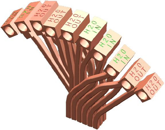
This is a preliminary 3D model showing the bussing detail on the Q2 magnet coils. The connections make an electrical circuit so that all 9 turns are in series on each coil. Simultaneously, the connections gang the leads up in pairs so that each turn has its own supply and return for cooling water. The connections reduce the unwieldy 9 hoses in and 9 hoses out to 5 hoses in and 5 hoses out per coil!!
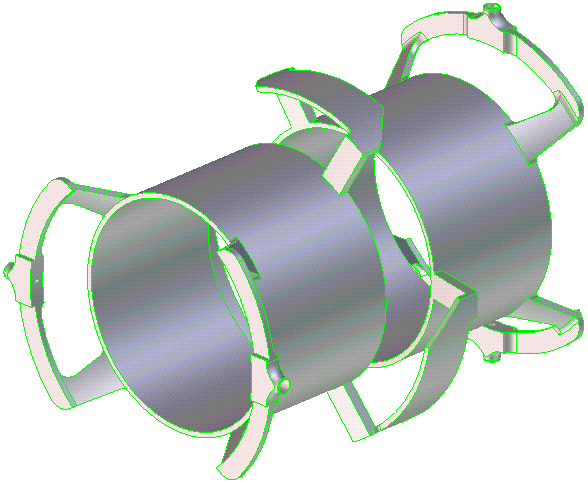
This is a SolidDesigner 3D model of the logitudinal kicker electrode for the B-Factory HER. The electrode design is similar for the LER. The purpose of the kicker is to "kick" straggling particles forward and "kick" fast particles back to compress the logitudinal distribution of the particle packets. This is done by applying a time varying current to the electrode which sets up a varying electric field. The changing electric fields are timed so that they kick particles forward or backward as a given packet screams through at nearly the speed of light. John Corlett and Bob MacGill designed and tested a prototype of the electrode. I made this 3D model for the purposes of making detail drawings for manufacturing.