All you need to do is use standard Windows-type commands to copy and paste existing ME10 geometry into SolidDesigner. The copied profiles will be immediately reused by SolidDesigner to generate your first 3D model.
Actions performed in this section:
- Loading of an existing ME10 drawing
- Copying and pasting of 2D geometry
- Creation of a 3D part based on 2D geometry
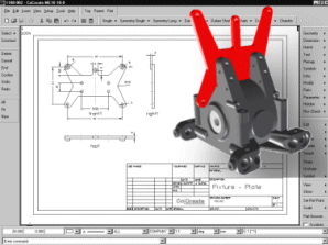
Return to SolidDesigner.
Hide all parts in the part browser.
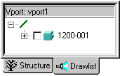
Load certain components that will serve as a basis for positioning the parts.
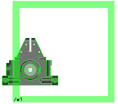
Select the part as shown to activate it
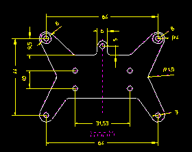
Copy the contour:
![]()
Click the outline contour
and the inner holes
![]()
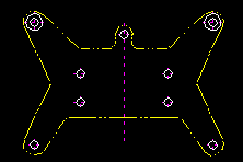
To use this drawing as a basis for new designs, you will adapt the newly created geometry.
Catch center point using [Ctrl], [Shift] and the left-hand mouse button, and click on the middle hole
Catch center point using [Ctrl], [Shift] and the left-hand mouse button, and click on the middle hole
Enter a value of 15 in the user input line and press [Enter]
Select the horizontal construction line
Click on a point on the upper side of the line
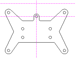
![]()
![]()
Drag a rectangle to capture all the required geometry
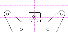
![]()
![]()
Select the intersection points of the construction lines
![]()
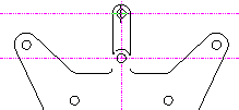
Click on the
picture to get more information
Make
sure that the part 1100-002 is active.
Click on the part name with the
right-hand mouse button and select the Set Active
option .

![]()
![]()
Go to ME10 and measure the
distance on another view of the drawing.
![]()
Measure the width of the part on the drawing .
Copy the value using [Ctrl
C].
Return to SolidDesigner.
Click in the distance field.
Paste
the measured value using the
right-hand mouse button and press
[enter].
Deselect the option ![]()
![]()
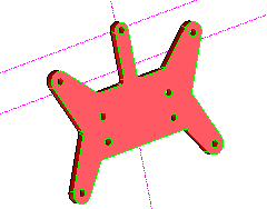
Go to ME10
Return to SolidDesigner
Select direction -W
Deselect the option
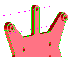
Click on the picture to get more information

