In this section, you will learn how to create a 2D profile that can then be used to create the 3D part shown below.

If you are familiar with ME10 or other 2D CAD systems, you will benefit from being able to use similar commands to create 2D geometry within SolidDesigner.

If you are a new CoCreate user, you will see how easy it is to create 2D geometry without defining any constraints or parameters.

Actions performed in this section:

  • Familiarization with the basics
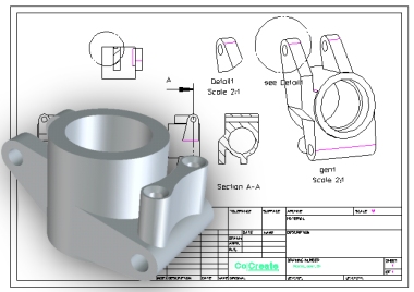
  • Creation of 2D geometry

Click on the arrow to go to the next step 


What is a workplane?  

A workplane is an infinite, transparent plane that can be positioned anywhere in 3D space, even within a part. 

It is in many ways comparable to a drawing board. The workplane contains the 2D geometry.


What is a 2D profile?

You will define the 2D geometry inside the active workplane and use this geometry for different purposes, including machining operations. 
To be valid for a machining operation, a 2D profile must be a closed contour. 

Both construction and geometric entities can be manipulated. Construction lines can serve as base lines to support the creation of real geometry.


Where do I enter values?
SolidDesigner has a user input line at the bottom of the screen where you enter values

Don't forget to press [Enter] to validate your entry.


Click on the arrow to go to the next step 


Now, start working as if you were using your current 2D system, drawing the construction lines that will make subsequent creation of the 2D profile very easy.


Infinite Line
Type  0 38 in the user input line and press [Enter].
Infinite Line
Type 0 4 in the user input line and press [Enter].
Construction Circle
Type 4
in the user input line and press [Enter].
Click point locations
P1 and P2 as shown.


     Click on the arrow to go to the next step 


Now, create the complementary construction tangent lines that will support the outer profile.


Infinite Line
Click on the left side of the top circle
Type
63 in the user input line and press
[Enter]
Click on the left side of the bottom circle
Type
103 in the user input line and press
[Enter]


To adjust the view, click the zoom icon.


     Click on the arrow to go to the next step 


Now, follow the sequence to create 2D geometry lines using 2D modeling commands.


Click on point P3 as the starting point.
Pick the lines in sequence as shown


   Click here to go to next chapter...