![]()
The plastic features that you can create are listed in the Plastic Feature Browser. You select one to open its dedicated creation menu, which displays a graphic in which the specifiable parameters are labeled. Use these indicators as a guide when entering or changing variables.
Mold Design Advisor provides a number of commonly-used plastic features that you can add to your models. Since the advisor uses calculation rules and defaults to create the features, you need only enter the independent values. However, at any time it is possible to "override" the rules.
The calculation rules, formulae, and default values are contained in a series of LISP customization files in the following directory:
.../personality/sd_customize/MoldDesignAdvisor/
There are four types of features available, and they are described in this page:
Plastic features are treated similarly to other features as regards
modifying, deleting and displaying them; see
Working with Plastic Features below.
You can create solid, simple and screw bosses, shown from left to right in the graphic below:

To create a boss, you first select the calculation rules (the group of formulae) used to determine the variables during the calculation of the boss. Then you specify its center point and direction, and the thickness of the reference wall. For simple bosses, you also specify the hole diameter, and for screw bosses, the screw diameter. The other parameters are selected according to the selected calculation rules, but you can change these if necessary.
If any of the parameters you enter breaks a rule, Mold Design Advisor issues a warning informing you of the allowable values for the parameter. You can always revert to the Advisor-determined default values, which replace any values you have entered.
Ribs are created according to the following template:
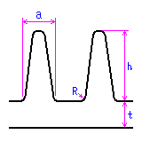
To create ribs, first select the calculation rules used to determine the variables during the calculation of the ribs. Then specify the workplane containing the rib profile, and specify a direction for the ribs. You can choose whether or not to extend the ribs to meet the walls of the mold part.
Now enter the thickness of the reference wall, from which the maximum allowable height of the ribs is calculated. You can optionally enter a new height value, but if the calculated maximum height is larger than the specified value, Mold Design Advisor issues a warning. All other rib parameters are selected according to the selected calculation rules, but you can change these if necessary.
If any of the parameters you enter breaks a rule, Mold Design Advisor issues a warning informing you of the allowable values for the parameter. You can always revert to the Advisor-determined default values, which replace any values you have entered.
Gussets are created according to the following template:
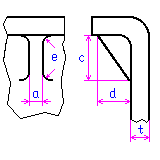
To create gussets, first select the calculation rules used to determine the variables during the calculation of the gussets. Then specify two different reference faces to locate the gusset, and specify a positioning point and direction for the gusset on the first reference face.
As with bosses and ribs, you now enter the thickness of the reference wall, from which the other parameters are calculated according to the selected calculation rules. You can change these if necessary.
If any of the parameters you enter breaks a rule, Mold Design Advisor issues a warning informing you of the allowable values for the parameter. You can always revert to the Advisor-determined default values, which replace any values you have entered.
In addition to bosses, ribs and gussets supplied with Mold Design Advisor, you can also create customized plastic features. Note that you must first register customized features in a customization file found within the SolidDesigner installation directory:
.../personality/sd_customize/MoldDesignAdvisor/mold_customize.lsp
The process for creating such features follows a general pattern: You load a tool part (face part or solid part) into SolidDesigner, specify a reference face on the mold part to which the plastic feature is to be attached, and then paste specified faces of the tool onto the mold part.
Plastic features can be renamed and copied in the same way as other SolidDesigner custom process features. Also you can report, highlight, and show plastic features, and change their properties, as you would with custom process features.
Deleting plastic features is done slightly differently. When you delete plastic features with the Delete option in the Plastic Features menu, both the feature and the actual physical geometry of the feature are deleted.