![]()
This the third page that discusses the core and cavity functions of Mold Design Advisor. Here we look at parting and fill surfaces and creating forms.
Exercises:
A parting surface is created from the parting line and pull direction of a molded part, and is extended to the mold block. You can specify one of six modes - perpendicular, parallel, anti-parallel, normal, tangent and constant - to create the parting surface, although individual edges of the parting line can be given a different mode.
A filling surface is created by specifying a feature having edges defining an open loop, or by selecting those edges manually. If there are multiple open loops on the selected feature, you must select the correct loops for the fill surface.
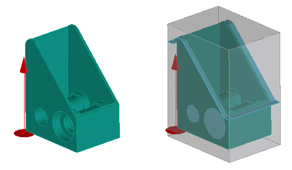
For example, the following shows a mold part within the mold block, showing fill surfaces and the parting surface:

You can create a solid part from its core or cavity feature, parting surface, and fill surface. The resulting solid is the union of the respective faces trimmed at the mold block.
Sliders are created by specifying the slider feature (defined by manual part-splitting), the direction of the slider and the fill surface. Again, the slider is trimmed at the mold block.
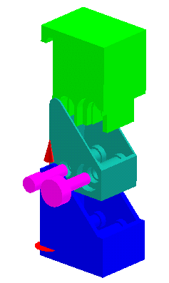
The following graphic shows a part (middle), with its cavity (above, in green), core (below, in blue) and two sliders (left, in magenta):

In the following exercises, you will create two fill surfaces in our part, followed by four sliders, then a parting surface, and finally the core and cavity forms.
Create the fill surfaces for the slider:
TUT90-MDA-coring-ex3.pkg
from the Parts directory, which contains the part already prepared
for this exercise.


Repeat the above procedure to create another filling surface in the other undercut containing two slider features:

Create four sliders:

Repeat the above steps on the other three slider features, using each fill surface twice, to create a total of four sliders. They are pictured here copper-colored and slid out of the part:

Create the parting surface:

Before you can create core and cavity forms, you must deal with the two undercuts in the part. You can follow one of two possible methods:
Core1, and you enter this name in the Feat Name
box after selecting Core from the Type list. Then you
click to add faces by Feature, and select an undercut feature
from the table. Repeat this to add the other undercut to the core:


Create the core form:

Create the cavity form in the same way, clicking a face belonging to the cavity feature:
